Spirometry: A Historical Gallery Up to 1905

Spirometry: A Historical Gallery Up to 1905 150 150 IEEE Pulse
Author(s): Richard Johnston, Max Valentinuzzi

“And the Lord God formed the man from the dust of the ground and breathed into his nostrils the breath of life, and the man became a living being.” (Genesis 2:7)
In Latin, spirare means to breathe; hence, spirometry deals with the measurement of breath, which is the most common way to evaluate pulmonary function. The volume or flow of inhaled or exhaled air is so quantified, offering values that permit an assessment of respiratory performance in health and disease. Asthma, emphysema, pulmonary fibrosis, and obstructive lung pathologies can be gauged in their respective stages. Spirometry is an old procedure still in use that is simple and inexpensive but highly significant in health care.
This column has been designed in a somewhat different format than the usual “Retrospectroscope” columns, for it takes the appearance of a gallery, mostly showing pictures along with brief descriptions in which their respective origins are given, when possible. It must be underlined the great difficulty of searching for this kind of old information, which deals with a highly dispersed subject and innumerable contributions, far more than those included herein; we decided to leave only those deemed relevant. Hence, the reader should be indulgent with us if he or she detects that something is missing. Most of this material was provided by Richard Johnston, who has accumulated a large amount of professional experience in this area over the years and has collected these illustrations. The reader may assume the stance of a visitor entering a museum to get a historical spirometry bird’s-eye view. We hope you enjoy it.
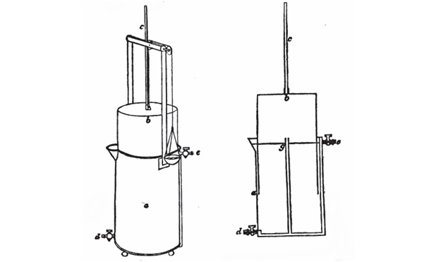
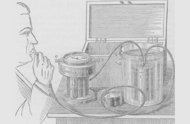
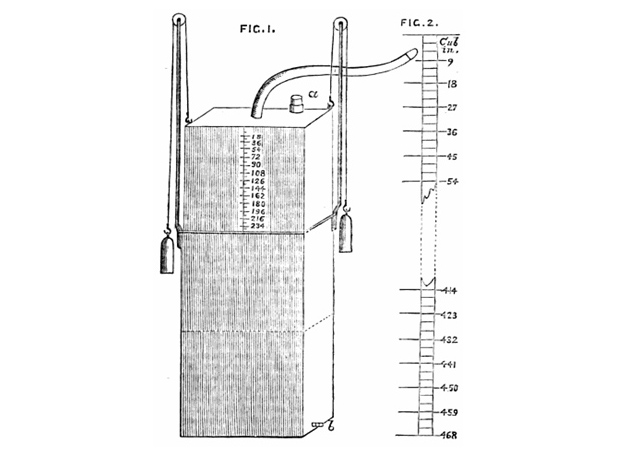
The first attempt to measure pulmonary volumes goes as far back as the second century, when Galen (Claudius Galenus of Pergamo, A.D. 129–circa 200–216), the famous Greek physician, tried to determine respiratory volume by having a child breathe into a bladder. A long time after, the Napolitano Giovanni Alfonso Borelli (1608–1679) sucked a column of water into a cylindrical tube and measured the air volume displaced by the water. He took care to close his nose to avoid leaks, still a point to consider today. Humphry Davy (1778–1829) measured the residual volume of his own lungs in 1800 by inhaling a hydrogen mixture contained in a mercurial air holder. Using the same principle, Nestor Grehant (1838–1910), in 1864, determined the functional residual capacity and the dead space volume; both used forced breathing. A schematic of the oldest unit we could track, called the gasometer, is depicted in Figure 1.

Figure 1: A gasometer from A Manual of Chemistry, p. 82, by William Thomas Brande, 1819, published by J. Murray, Albermarle Street, London. This is perhaps the oldest piece in the historical lineage.

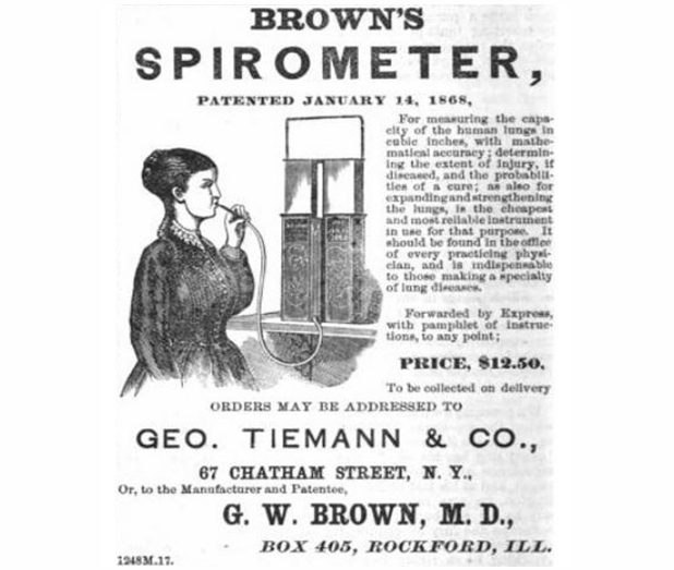
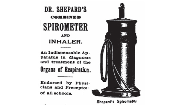
However, the true beginning of modern pulmonary function testing (PFT) can be dated to 1846, when John Hutchinson, an English physician, invented the spirometer by taking a common gasometer and turning it into a precision instrument for measuring the volume exhaled by human beings. Hutchinson’s genius, the source of inspiration for those who followed him, was in performing vital capacity measurements on 2,130 individuals, showing a correlation between height, age, weight, and the volume of the vital capacity. He coined the term expiratory vital capacity. His work inspired other researchers and inventors. Within a few years, improved versions of his spirometer appeared across Europe and the United States (Figure 2). No doubt, Hutchinson deserves a prominent position in this area and recognition to his memory must be rescued.

Figure 2: John Hutchinson’s spirometer from “On the Capacity of the Lungs and on the Respiratory Functions with a View  of Establishing a Precise and Easy Way of Detecting Disease by the Spirometer,” Medico-Chirurgical Transactions, pp. 137–252, 1846. Volume and issue are not available.
Figure 2: John Hutchinson’s spirometer from “On the Capacity of the Lungs and on the Respiratory Functions with a View of Establishing a Precise and Easy Way of Detecting Disease by the Spirometer,” Medico-Chirurgical Transactions, pp. 137–252, 1846. Volume and issue are not available.

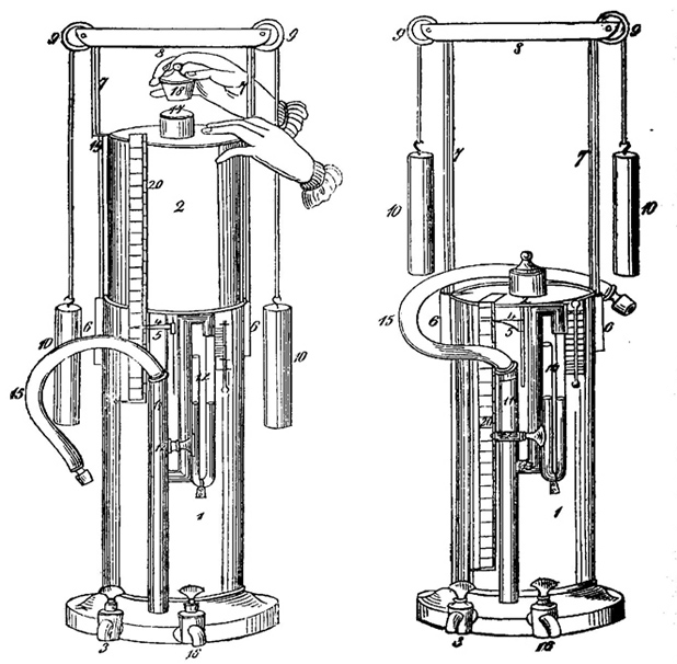
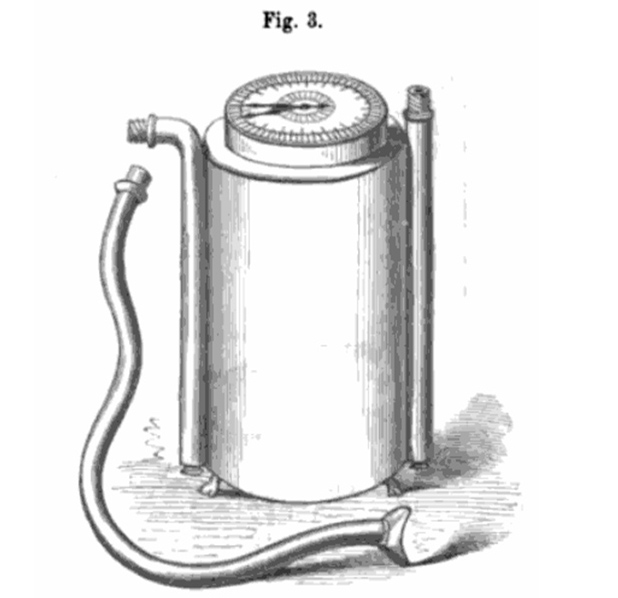
Notably, only four years after Hutchinson’s treatise, his original design for the spirometer appears to have already been modified. The developer of this updated unit is unknown, and he was not named in a German text describing it (Figure 3).

Figure 3: The improved spirometer of an undetermined author. From Figure 2 of an unnumbered endplate in “Die Erkenntniß der Krankheiten der Brustorgane aus physikalischen Zeiche und/oder Auskultation, Percussion und Spirometrie. Nach Heribert Davie’s Vorlesungen und eigenen Beobachtungen” [knowledge of the diseases of the thoracic organs from physical signs and/or auscultation, percussion, and spirometry. From the lectures and observations] of Johann Friedrich Hermann Albers, 1850, published by Adolph Marcus, Bonn.

 
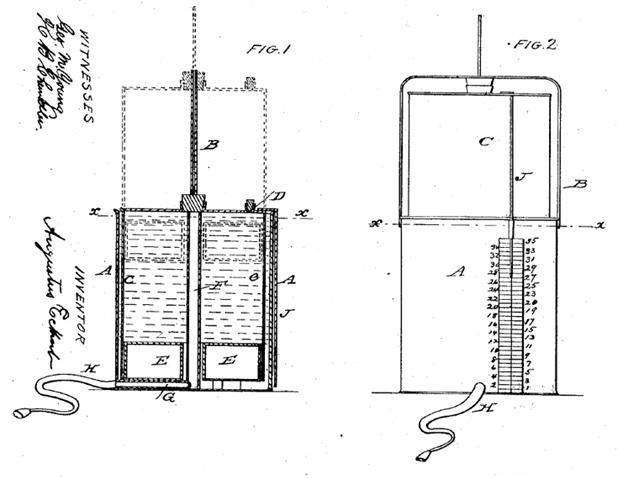
There was a ten-year gap until a noncounter-weighted, water-sealed spirometer was presented (Figure 4). It featured a guide rod (labeled “B” in the figure) to keep the inner bell straight and an air-filled, water-tight chamber in the rim of the bottom of the inner bell (buoy “E”) that served the same purpose as a counterweight. The cork (labeled “D” in the figure) was removed after a vital capacity effort had been made and recorded to allow the bell to be returned to its lower position.

Figure 4: A spirometer. U.S. Patent 26754, by Augustus Eckert, of Dayton, Ohio, filed in 1860.

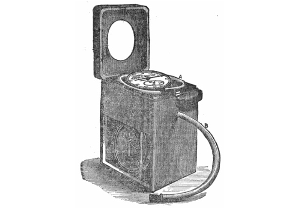
After three years, we found Bowman’s unit, which is depicted in the sketch in Figure 5Figure 6 is not very clear, but it shows an unexplained drawing of a unit attributed to a certain Dr. W. Weir Mitchell, done in 1863, the same as Figure 5. It was a spirometer, made based on the plan of a dry gas meter, that was employed in Germany for some time. Apparently, it was altogether simpler in its management than Hutchinson’s instrument and afforded accurate results, so it was discussed in A Treatise on Hygiene.

Figure 5: W.E. Bowman’s spirometer from The Half-Yearly Abstract of the Medical Sciences: Being a Digest of British and Continental Medicine, and of the Progress of Medicine and the Collateral Sciences, vol. 38, p. 132, 1864. The original article is by W.E. Bowman, from the Canada Lancet, 15 June 1863. The article included construction instructions, stating, “A cheap spirometer may readily be made from two tin vessels similar to shape of the ones figured in the accompanying woodcut.” Observe its calibration in pints and fluid ounces on the right-hand side.

Figure 6: Dr. W. Weir Mitchell’s spirometer from A Treatise on Hygiene, by William Alexander Hammond, published by J.B. Lippincott & Co, Philadelphia, 1863, p. 42.

To continue chronologically, Figures 7-10 depict units that appeared more or less simultaneously.

Figure 7: A. Gardiner Brown’s spiroscope from The Science and Practice of Medicine, vol. 2, by ­William Aitken and Meredith Clymer, published by Lindsay and Blakiston, Philadelphia, 1868, p. 540. “Brown’s spiroscope is a new and efficient instrument for ascertaining the breathing capacity. It is a wet meter, 6.5 in², having a dial with two registers, revolving from left to right, marking in a complete revolution 100 and 1,000 in³, respectively, and a few feet of vulcanized India-rubber tubing to breathe through.”

Figure 8: G.W. Brown’s spirometer, 1868. The drawings are from his patent (#73229). A rectangular water-sealed spirometer made of a tin plate with dimensions listed as 8.5-in wide, 4.5-in deep, and 13.5-in tall. The wire handle that projects over the top was a guide for the inner spirometer reservoir (bell). The index (ruler) was attached to the inner reservoir and had a cover that protected it from wear. 0.25 in of vertical movement was equivalent to 8 in³.

Figure 9: G.W. Brown’s spirometer, advertisement from The Medical Gazette: A Weekly Review of the Medical Sciences, vol. 5, H.W. Turner, Ed., 1870, p. 134.

Figure 10: Casella’s spirometer from The British Medical Journal, 28 Sept. 1872, p. 356. “It is constructed on the principle of Casella’s sensitive air meter, first constructed for Dr. Parkes for measuring flow at the Netley Hospital, and now largely used in all public establishments. It consists of finely balanced circular air sail, which drives a hand over a dial, the graduations being obtained, by actual experiment, by means of machinery made for the purpose. The dial shows the force and amount of respiration and capacity of the chest.”

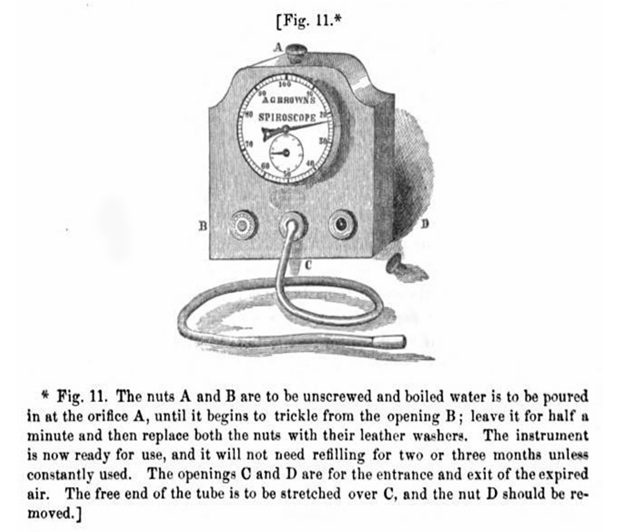
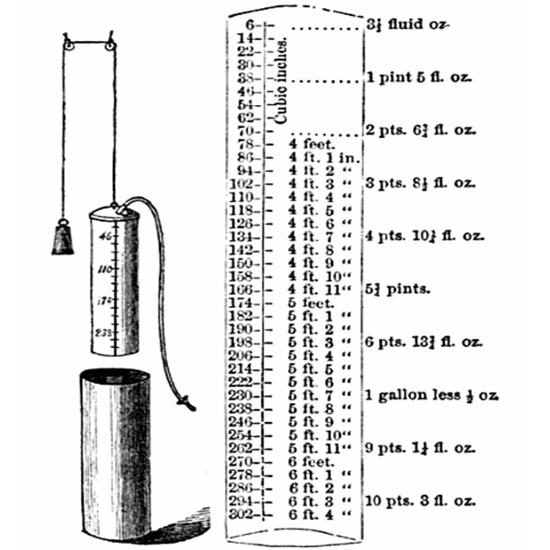
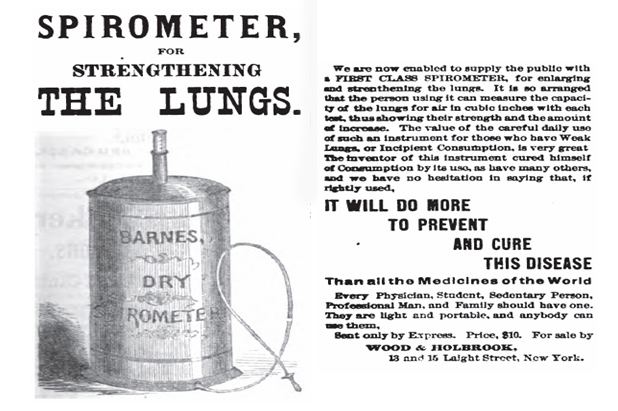
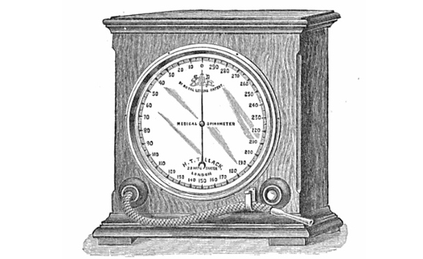
A description of the spirometer shown in Figure 11 is found in The Science and Practice of Medicine, vol. 2, by William Aitken and Meredith Clymer, published by Lindsay and Blakiston, Philadelphia, 1868, p. 540 as follows:

The Lung Tester of A.P. Barnes (to be had of Messrs. Codman & Shurtleff, Boston) is the simplest and cheapest of all spirometric instruments. It consists of a cylindrical bag of India-rubber cloth, closed at each extremity by a disk of wood, and furnished with two metallic tubes; one tube enters laterally at the bottom and is about 3 in long; the other, vertical, is about 12 in long and graduated, and inserted in the centre of the upper disk. A flexible tube of proper length with a mouthpiece is stretched over the outer aperture of the lower metal tube, and through this a forced expiration is made; the expired air fills, more or less, the bag and the vital capacity is recorded on the upper tube, which is forced up as the bag expands. The bag is enclosed in a tin cylinder, shut at both ends with two holes for the tubes.

Figure 11: A.P. Barnes’ spirometer advertisement from The Herald of Health, Jan. 1875, p. 93.

The reader should proceed to Figures 12–17, so closing the chronological sequence of events.

Figure 12: Victor Jagielski’s spirometer from The London Medical Record, published by Smith, Elder & Co, London, 15 July 1879, p. 293. “The instrument has three horizontal compartments, one above the other. The lowest compartment is open to view having two glass windows, and is divided by a vertical partition, on either side of which there is a round diaphragm, containing a space of 10 in³ each when expanded or filled; these two chambers can be seen working alternately during expiration and inspiration, the one contracting when the other expands.”

Figure 13: Rattray’s spirometer from “A Combined Spirometer, Aspiratory, and Aeroscope,” by Alexander Rattray, MD. The Lancet, 28 Dec. 1882, p. 915. “For stability and economy of space the cylinders are square; the inner of the thinnest—i.e., lightest—sheet zinc, 6 ×6 in wide, 13 in high, and accurately counterpoised by weights of lead covered by brass or copper, hanging by 24-in-long silk or catgut cords over two pulley tipped 0.25-in brass rods, 14 in long, placed at opposite corners. The breathing tube, 1 in in diameter and 28 in long with an ebony or ivory mouth piece, should be attached to the center of the inner cylinder, either by a simple or screw attachment.”

Figure 14: Stanley’s spirometer from The Journal of the Royal Anthropological Society, 1891, vol. 20, p. 29. “It consists, as in the gas meter, of a light closed fan wheel, with cup fans, revolving nearly under water. The expelled air is projected into one side of the fan wheel. This side rises immediately by the minus gravity of the air to that of the surrounding water, while in the meantime another fan comes to position to receive the next quantity of expired air, and so on continuously so long as the lungs expire breath at a pressure beyond the small frictional resistance of the apparatus.”

Figure 15: An advertisement in 1892 of Shepard’s spirometer from Homœopathic News: A Monthly Homœopathic Medical Journal, vol. 21, no. 1, p. 291. A water-sealed spirometer with a direct reading scale on a rod attached to the bell.

Figure 16: Denison’s spirometer. The commercially manufactured version from The Mechanics of Surgery, Hammond Press, Chicago, 1899, by Charles Truax, p. 48. “The spirometer I here show you is of my own experimenting, and I will trust it will commend itself to you as a faithful measurer of vital capacity. When full it is a hollow cylinder, 11.28 in in diameter, standing on end, the two ends being closed, and the sides made of one piece  of light, impervious cloth. The structure is so light as to give little or no resistance to the expired breath.”
Figure 16: Denison’s spirometer. The commercially manufactured version from The Mechanics of Surgery, Hammond Press, Chicago, 1899, by Charles Truax, p. 48. “The spirometer I here show you is of my own experimenting, and I will trust it will commend itself to you as a faithful measurer of vital capacity. When full it is a hollow cylinder, 11.28 in in diameter, standing on end, the two ends being closed, and the sides made of one piece of light, impervious cloth. The structure is so light as to give little or no resistance to the expired breath.”

Figure 17: Boudin’s spirometer from Rainal Brothers, Leon & Jules, Medical Equipment Catalog, 1905, p. 380. Originally developed by Boudin in 1854, this spirometer consists of a rubber bulb. A rod with a scale is attached to the top and is used to measure the exhaled volume. This version was manufactured and sold in 1905.

Discussion

Water-sealed spirometers, distinctly recognizable as descendants of Hutchinson’s spirometer, are still being manufactured and sold, although primarily as teaching instruments. This article presents in a summarized, gallery-like way the evolution of spirometers from the beginning of their scientific and technological development until the start of the 20th century. The 19th century was prolific in the subject, as more than 50 variations on spirometers can easily be found that are perhaps less significant than those shown here but of interest for the history researcher. Some of these instruments were extremely simple and ingenious, while others display good advancements and sophistication. Several contributors worked for a long time, indicating the amount of concern the subject raised since breathing is essential for life. The personnel involved in emergency services know well that the two vital signs to check are heartbeat and respiration. Nonetheless, the reader will easily detect in some of the inventors an overt commercial tendency, even some signs of sheer quackery, but science and technology have always been disturbed by this kind of undesirable noise. Truth in the end always wins.
To close the article, the subject may attract the historian or the bioengineer, but why not high school students looking for science fair projects? How much fun (and learning) can be collected when trying to build one of these instruments?

Acknowledgment

All images in this article are courtesy of Richard Johnston.