Blood flowing to the brain keeps it alive, while electrons flowing to inhabited civilized places keep them active, leading to greater understanding of the world. What, however, of those many human beings still confined to distant hostile regions, unaware of the magic of electricity now over a century old … How do they live, what can they do, and what do we, happy people, do for them?
The word analogy is a synonym of likeness, resemblance, similitude, or affinity and involves two concepts being placed side by side, as in a comparison [1]. The workings of nature and those of human societies are amenable to such analogous comparison—even though the evolution of the natural world obviously spans millions of years [2], while human societies are much younger, relatively puppies by comparison. This article considers two interesting examples from these two realms that show remarkable similarities (possibly a result of sheer chance), i.e., a circulatory brain anastomosis, the circle of Willis (CW), and modern power transmission- distribution systems in the ring arrangement. Remember that electric networks handle the flow of charges [say, in coulombs per second (C/s) or electric charge per unit time, which is current), whereas hydraulic systems deal with fluid flow [say, in liters per minutes (L/min) or volume/unit time or fluid mass/unit time]. Hence, these systems too are analogous, a well-known fact often mentioned by instructors of electrical engineering courses.
Cerebral circulation refers to the movement of blood through the network of blood vessels supplying the brain, the primary governing organ that makes us human beings. The rate of cerebral blood flow in adults is typically 750 mm/min, representing about 15% of cardiac output [3]. The brain is very vulnerable to compromises in its blood supply; consequently, its circulatory system has many safeguards, of which the CW is one. Brain circulatory failure results in cerebrovascular accidents, commonly known as strokes, a health situation of considerable concern.
Circle of Willis
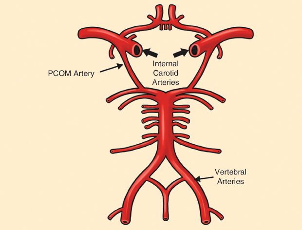
The CW (Circulus arteriosus cerebri) sits at the base of the brain (Figure 1). It was named after Thomas Willis (1621–1675)— an English doctor who played an important part in the history of anatomy, neurology, and psychiatry—by his student Richard Lower (1631–1691), also an English physician, because Willis had described such a vascular ring [4]. (Lower significantly influenced the development of medical science and is most remembered today for his contributions to transfusion and the function of the cardiopulmonary system.)
The CW encircles the stalk of the pituitary gland and provides important communications between the blood supply of the forebrain and hindbrain (i.e., between the internal carotid and vertebrobasilar systems). The circle starts where the internal carotid artery enters the cranial cavity bilaterally and divides into the anterior cerebral artery (ACA) and middle cerebral artery. The ACAs unite as the anterior communicating (ACOM) artery, constituting the anterior circle half section. The posterior circle section derives from the left and right vertebral arteries; thus, there are left and right posterior cerebral arteries (PCAs) that complete the circle by joining the internal carotid system anteriorly via the posterior communicating (PCOM) arteries (Figure 1). Thus, the brain’s blood supply comes from four inflows: the two internal carotids and the two vertebral arteries.
Figures 2 and 3 show different views that help explain the overall (and rather complex) disposition of the network. The left and right internal carotid arteries arise from the left and right common carotid arteries, and the vertebral arteries originate at the subclavian arteries.
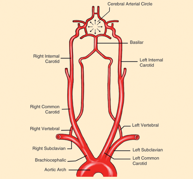
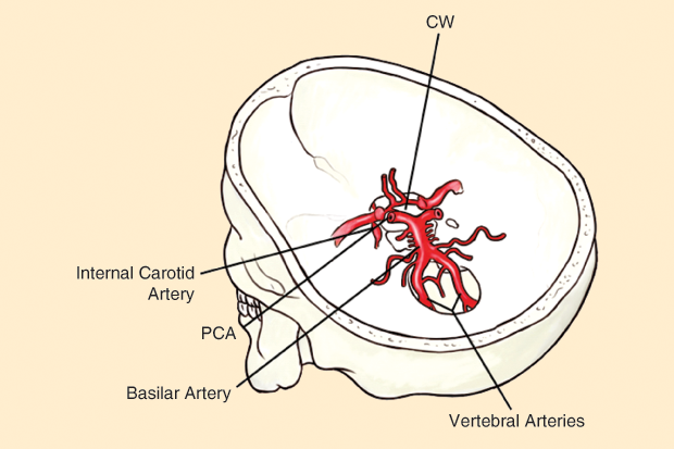
One can visualize the CW by imagining a crown inserted in the brain horizontally. Two main arteries, the internal carotids, send flow to the frontal area, while two less important vessels, the vertebral arteries converging to the basilar artery, feed the posterior side. Such a crown- or ring-like disposition distributes the blood flow very efficiently and rather safely throughout the cerebrum. Figure 3 supports this description, offering a different way of looking at the network.
Other arteries are also part of the circle and simply complete the arterial description: the ACAs (left and right), the ACOM artery, the PCAs (left and right), the PCOM arteries (left and right), and the basilar artery; the latter is extremely important because it collects blood from the two vertebrals, meaning that feeding from these posterior inflows actually converges to a single one in the end.
The CW provides backup circulation to the brain. In case one of the supply arteries is occluded, the circle has interconnections between the anterior and the posterior cerebral circulation along the floor of the cerebral vault, supplying blood to tissues that would otherwise become ischemic. This is a superb design, worth analyzing from an evolutionary viewpoint. If, for example, one of the feeder arteries is occluded, blood flow to the brain continues without any harm to its tissues. The return venous drainage of the cerebrum can be separated into two subdivisions known as superficial and deep. Detailed descriptions can be found in anatomy textbooks or easily accessed via the Internet (which is not essential for the purposes of this article).
Ring Electric Power Systems
Distribution and transmission of electric power is accomplished by networks consisting of stations or substations, feeders, transformers, and service mains. The stations or substations generate power, say, using fuels of different kinds, from traditional oil to hydraulic or atomic sources. (Solar and wind energies are good candidates but still represent a very minor percentage of overall installed generators.)
Feeders are lines transferring power from a station to a distribution transformer, a final branch circuit, or any other device. The transmitted electric power is stepped down in substations for primary distribution purposes [5]. Often used are ring distribution systems, conceptually very similar to the CW described previously (Figure 4). Distribution transformers are mainly of the three-phase type. The secondary transformer is connected to distributors, and different consumers are fed by means of the service main. These service mains are tapped from different points of the distributors.
![Figure 4: The interconnected ring power system (IRPS). The quadrangular feeder ring is energized by four generating stations, S1–S4. After passing through distribution transformers, the two horizontal and two vertical distributing lines (originating at the middle point of each quadrangle segment) branch off to the customers’ loads (homes, factories, shops, and so on). The IRPS has two important advantages: better service reliability and improved efficiency (based on the fact that any area fed from one generating station during peak load hours can be fed from the other generating station) [6].](https://www.embs.org/wp-content/uploads/2018/02/retrospectroscope04-2772138.png)
The drawbacks of the initial, and perhaps more traditional, radial electrical power systems were overcome by ring systems. Here, one ring network of distributors is fed by more than one feeder. In this case, if one feeder is under fault or maintenance, the ring distributor is still energized by other feeders connected to it. In this way, the supply to the consumers is not affected, even when any feeder is out of service. In addition, the ring main system is provided with different section isolates (cutoffs) at different suitable points. If any fault occurs on any section of the ring, this section can easily be isolated by opening the associated section isolators on either side of the faulty zone.
Thus, supply to consumers connected to the good zone of the ring can easily be maintained, even when one section of the ring is shut down. This also accomplishes a protective function. The number of feeders connected to the ring main electrical power distribution system depends upon several factors, such as maximum demand of the system, total length of the ring main distributors, and required voltage regulation.
Discussion
An ancient physiological system for distributing blood in the brain cleverly guarantees the fluid supply to this essential structure. However, the CW is not 100% foolproof because disease, unfortunately, finds its way to partially damage the organ or even end one’s life. Conversely, do we know how many times a particular individual was spared because of the ring arrangement or how many lives may have been prolonged by this beautiful distribution of the elixir of life to the brain?
Electric Power Networks – Early Years
A little digging into the historical development of electric power networks is appropriate here, while recognizing that knowledge of electricity as a static phenomenon represents centuries of experience and experimentation. For example, various species of electric fish likely shocked more than one human being trying to have them for lunch; on the biological side of science, such aquatic animals have a modified group of muscle or nerve cells that became specialized for producing bioelectric fields stronger than those that normal nerves or muscles produce. Typical examples are the electric eel, electric catfish, and electric ray, which can generate amplitudes of 10–600 V and are able to sustain currents of up to 1 A.
After devising a viable light bulb in 1879, Thomas Alva Edison (1847–1931) developed the first large-scale electric illumination system (in Manhattan, New York). When service began in September 1882, there were 85 customers with 400 light bulbs. Each generator produced 100 kW, enough for 1,200 incandescent lights, and transmission was at 110 V via underground conduits [7]. This suggests the relatively short history of electric power lines (which entered their second century not too long ago) and the still shorter history of the concept of ring distribution.
The ring concept belongs fully to the 20th century. The first power ring systems were installed in Europe (France and Northern Italy) during the first decades of the last century, and Giovanni Ossana (1870–1952) may well have been among the leading engineers involved in their study and design.
Chances are that no connection ever existed between the physiological brain ring and the much newer technological ring. Could we dream that an electrical power engineer knew some circulatory physiology and was aware of the CW? Perhaps, but we do not know, and this falls into pure speculation. Nonetheless, both systems show similar behaviors, and that fact is interesting in itself (or, at least, appears as a curious happenstance).
Can anything be learned? Yes, nature often produces designs that the human mind rediscovers ages later, finding them quite useful for other applications: biomimetics, the imitation of systems and elements of nature for the purpose of solving human problems at macro and nanoscales, comes to mind as an example; the term was coined by American scientist and inventor Otto Schmitt (1913–1998) during the 1950s [8]. Nature, indeed, has solved problems such as self-healing abilities, environmental exposure tolerance and resistance, self-assembly, and harnessing solar energy, among many others.
The first electric networks operated in direct current (dc) and low voltage in the late 19th century in Europe and the United States. The International Exhibition of Electricity of Paris, held in 1881, displayed for the first time an installation showing the distribution of electrical energy powered by two dynamos [9]. The use of transfomers was key in giving alternating current (ac) essential advantages. The first experimental ac transmission via overhead lines appeared in 1891, spanning Frankfurt and Lauffen, Germany [10]. This power transport line was crucial for the development of electricity, connecting generating stations far away from consumption centers and showing the advantages of three-phase ac systems, which combine production, transmission, and distribution within a single technological system. The operating voltage was 20 kV and 40 Hz to transmit 200 kVA. To improve transmission efficiency, voltages were increased in newer systems to 25 kV in 1896, 110 kV in 1908, and 150 kV in 1913.
The invention of insulators was critical in making clear the significance that materials have in any technological development. The expansion process of electric energy, with higher power transmission over long distances between generation and consumption centers, has led to several sources being connected to a single electric system, giving birth to the interconnected ring power system (IRPS). Such systems were studied in the early 1900s in Europe and in the United States. The operation of more than one alternator in parallel presented several serious problems, particularly the hunting phenomenon produced by oscillation between machines, which has been analyzed by several experts [11]–[13].
Electric Power Networks — Early 20th Century
After World War I, the development of IRPSs was intended to reduce local shortages and costs because the construction of overhead power lines required less time and money than the construction of power stations. Furthermore, interconnection allows replacing and/or furnishing the power not being provided by machines that are out of service, assuring consistent power supply. It is amusing to suppose that nature “designed” the CW with a similar goal: reducing accidental blood shortages (or strokes) along with the cost of biological materials and that engineers followed a similar line of thought.
The fundamentals of mesh systems with several synchronous generators were well established in the 1920s, illustrating early on the need to regulate frequency and voltage, the basis of modern load-dispatch centers [14], [15]. Figure 5 depicts the original scheme designed in 1922 by Giovanni Ossanna (1870–1952), who had in 1899 published the still famous circle diagram for induction machines. (See [14] for an interconnected power system using devices and mechanical symbols well known at that time.) This figure has historical value because it shows a rudimentary first representation of an interconnected electric power system using symbols for mechanical devices, as the electrical symbols for ac grids were not yet in use. The gears and drive shafts are mechanical representations, which were substitute tools before the consolidation of electric circuit theory, and allowed one to explain the electrical behavior of several synchronous generators connected in parallel.
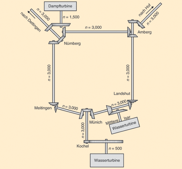
Figure 5 shows an interconnected power system with three generating plants in Bavaria, Germany; two hydropower plants, one in Kochel Lake and the other in Münich (Isar River); and one steam power plant in Nürnberg. Each power plant worked with a different number of revolutions (500 and 1,500) but with a single electrical frequency, and all were electrically interconnected to the same three-phase transmission system by means of transfomers. The system fed several towns and cities: Münich, Meitingen, Landshut, Amberg, Nürnberg, Hof, and Dettingen, with distances of more than 100 km. We suggest that readers refer to a map for the geographical location of these cities to gain a better idea of the system, taking into account the important changes such developments brought about 100 years ago.
Figure 6 shows the same power system as that in Figure 5, represented with modern electrical symbols, where the gears are replaced by busbar transformers and the drive shafts by overhead lines with inductances and capacitances. The mastery of the synchronous generators in parallel connection enabled the speedy development of interconnected power systems in ac with the operation of complex meshes having multiple loads, sources, and lines of different sizes. A few years later, long power transmission lines with a three-phase configuration were built in ac high voltage (220 kV in the United States in 1923 and 380 kV in Germany in 1930).
![Figure 6: The electrical circuit for the IRPS in Bavaria, Germany, as shown in Figure 5 (see [13]). Two hydroelectric power stations in Isar and Kochel and one steam power plant in Nürnberg operated together in parallel. The busbars of each town were connected by ac high-voltage overhead lines.](https://www.embs.org/wp-content/uploads/2018/02/retrospectroscope06-2772138.png)
Electric Power Networks — Later 20th Century
High voltage and IRPSs allowed considerable development of large ac power systems interconnecting several countries at a continental scale in the second half of the last century. The fast expansion of the ac systems (to the detriment of dc systems) was supported by ac’s advantages in terms of transforming the voltage levels at each grid busbar and breaking fault currents (both results deriving from Faraday’s law of induction [16]). However, dc systems have not disappeared, and now they seem to be making a technological renaissance with modern smart grids incorporating electronics devices, information technologies, and intermittent renewable sources.
The Analogy of the CW and IRPS
Comparing voltage and electric current with blood pressure and flow, it is possible to show that the CW operates in a way similar to interconnected electric systems, assuring current (blood flow) and voltage (blood pressure) at any point and at any time. The ac systems can be analyzed using the network nodal admittance formulation [17]. The nature of the system dictates that the solution to the network equations cannot be obtained in a closed form. This is the classical load-flow problem in large power systems, the nonlinear nature of which requires iterative techniques to obtain a solution.
Today, several numerical methods are available for solving the load-flow problem, e.g., the Newton–Raphson method [18]. Besides, now there are many commercial types of software to calculate voltage and current flow. The presence of capacitances and inductances makes it more difficult to obtain numerical solutions for load-flow problems in ac systems than in dc systems, but the nonlinear nature of the phenomenon is typical of meshed systems. In general, the nodalmatrix current equation for a grid with n buses identified by the indexes r and s can be written (see [17]) as
![]()
where I represents the current vector of n X 1 elements, V the voltage vector of n X 1 elements, and Y the admittance matrix of n X n elements
![]()
The summation runs over all buses connected to bus r.
When, rather than the bus currents, the bus powers Pr (active power) and Qr (reactive power) are specified, the static load-flow equation becomes
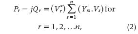
where
![]()
stands for the complex conjugate of the complex bus voltage Vr .
This mathematical tool allows the calculation of currents and voltages to assure the power flow and rated voltage in any point of an IRPS, just as the flow and pressure of blood must be assured in the vascular network of the circulatory system of the human body.
Conclusions
The similarities between the Willis cerebral ring and the modern power distribution–transmission electric system is indeed outstanding; one has ages of development behind it, and the latter is very young, as it barely reaches 100 years. Is this useful from the viewpoint of bioengineering or electrical engineering? The answer to such burning questions remains up to the reader. No doubt, it is at least interesting to highlight this surprising analogy.
References
- Definition of “analogy.” Dictionary.com. [Online].
- C. Darwin, The Descent of Man, and Selection in Relation to Sex. Baltimore, MD: Penguin, 2004 (first published in 1879).
- M. E. Valentinuzzi, Understanding the Human Machine: A Primer to Bioengineering (Series on Bioengineering & Biomedical Engineering), vol. 4. Singapore: World Scientific, 2004.
- G. Gupta. (2016, May 12). Circle of Willis anatomy. Medscape. [Online].
- Engineering and Technology. Online Electrical Engineering Study Site. [Online].
- History of electric power transmission. Wikipedia. [Online].
- Electric power transmission. Wikipedia. [Online].
- M. E. Valentinuzzi, “Otto Arnold Schmitt (1913–1998), a pioneer. Overview of his scientific production,” IEEE Eng. Med. Biol. Mag., vol. 23, no. 6, pp 42– 46, 2004.
- “Congrès International des Électriciens, Paris, 1881,” in Comptes Rendus des Travaux. Paris: G. Masson, 1882.
- “The history of CIGRE: A key player in the development of electric power systems since 1921,” in International Council on Large Electric Systems (CIGRE, Conseil International des Grands Réseaux Electriques). Paris: Springer, 2011.
- W. L. Emmet, “Parallel operation of engine-driven alternators,” in 157th Amer. Inst. Elect. Eng. Meeting, New York, 1901, pp. 745–751.
- H. C. Stone, “Some problems of power plants in parallel,” in Sect. Meeting Amer. Inst. Elect. Eng., Pittsburgh, PA, 1919, pp. 973–996.
- C. Steinmetz, “Stability of high power generating stations,” in AIEE Annu. Conv., 1920.
- J. Ossanna, “Das arbeiten von synchronmaschinen im parallelbetrieb [The work of synchronous machines in parallel operation],” Zeitschrift des Bayerischen Revisions-Vereins [J. Bavarian Soc. Rev.], 1922.
- A. von Meier, Electric Power Systems: A Conceptual Introduction. Hoboken, NJ: Wiley, 2006.
- J. C. Maxwell, A Treatise on Electricity and Magnetism, vol. 2. London, U.K.; New York: Oxford Univ. Press, 1904.
- M. El-Hawary, Electrical Power Systems. New York: Wiley, 1995.
- K. Atkinson, An Introduction to Numerical Analysis. New York: Wiley, 1989.