Noninvasive electrical stimulation of the central nervous system is attracting increasing interest from the clinical and academic communities as well as from high-tech companies. This interest was sparked by two landmark studies conducted in 2000 and 2001 at the University of Göttingen, Germany. Michael Nitsche and Walter Paulus showed that by passing a weak, almost imperceptible electric current between two electrodes on the scalp, they could alter the way the human brain responds to stimuli and that the effect persisted for some time after the current was stopped. These findings opened the prospect of therapeutic applications of transcranial direct-current stimulation (tDCS).
Since then, thousands of scientific reports have been published on the application of this neuromodulatory technique to healthy subjects and patients, mostly with promising results. Over 300 clinical trials have been completed, covering a wide range of conditions, such as pain, depression, poststroke rehabilitation, dystonia, multiple sclerosis, epilepsy, dementia, schizophrenia, autism, and attention disorders. More recently, direct current applied transcutaneously to the spinal cord ( tsDCS) has been used to modulate neural activity in spinal motor and somatosensory pathways, with potential applications in the treatment of spinal cord dysfunctions, such as spasticity or chronic pain.
Technology and Mechanisms of Action
Medical devices for noninvasive electrical stimulation are current sources that can deliver up to a few milliamps independent of the load impedance. They are powered by a small lithium-ion battery and are light, portable, and affordable. Examples of commercially available stimulators are Starstim [1] from Neuroelectrics [2], DC-Stimulator [3] from Neuro- Conn [4], HD-tDCS [5] from Soterix [6], and HDCkit [7] from Magstim [8].
How does it work? The electric field generated in the brain and spinal cord shifts the resting membrane potential slightly, thereby affecting the firing rate of many neurons. The ensuing long-term changes in neuronal excitability are thought to be due to N-methyl-D-aspartate receptordependent glutamatergic neuroplasticity and are similar to long-term potentiation and longterm depression. The effectiveness of this interaction depends on the strength of the electric field and on its orientation relative to neuronal compartments, among other factors.
Further progress in the application of noninvasive electrical stimulation requires a better understanding of how the electric field distributes in the brain and spinal cord and how it interacts with the central nervous system. This would enable optimization of the electric-field delivery at the target, thereby increasing the efficacy of stimulation and reducing the variability of its outcome. Computational models are the ideal tool to do this. One reason is that in vivo measurements in humans are impractical. The main reason, though, is that these models allow a systematic investigation of the effect of parameters such as electrode size and position or tissue conductivity on the electric- field distribution in the cortex.
New Simulation Tools
With this purpose in mind, we have developed realistic human models (digital phantoms) of the head and body that are suitable for simulations of noninvasive electrical stimulation of the brain and spinal cord. The basic steps are
- acquiring high-resolution anatomical MRI images with appropriate contrasts [for the head models, diffusion tensor data should also be acquired to incorporate white matter (WM) anisotropy into the model]
- segmenting the anatomical images into an appropriate number of tissue types (at this stage, the triangular surface meshes that separate the various tissue types are generated)
- adding surface meshes representing the electrodes
- assembling the surface meshes and generating a tetrahedral (volume) mesh.
The volume mesh is then imported into a finite element (FE) solver, conductivity values are attributed to each tissue type, and boundary conditions, such as electrode currents, are imposed. Finally, an iterative solver is used to calculate the electric potential, from which the electric field and current density can be obtained.
Technical Specifications and Results
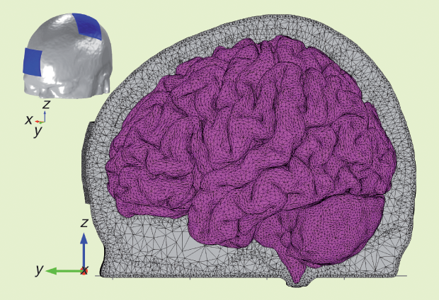
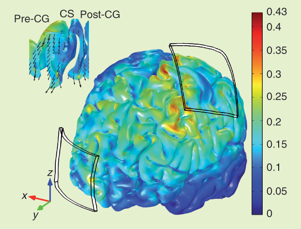
The head model was based on MRI images of a young subject. The data set included structural images with a resolution of 1 × 1 × 1 mm³, diffusion tensor data with a resolution of 1.25 × 1.25 × 3.5 mm³, and 20 gradient directions. The head was segmented into scalp, skull, cerebrospinal fluid (CSF), gray matter (GM), and WM. A sagittal view of the tetrahedral mesh of the head model with two 35-cm² electrodes is shown in Figure 1, and the electric field produced in the cortex by 1-mA tDCS is shown in Figure 2. Its magnitude reaches a maximum of 0.43 V/m in small areas on the gyri near the edges of the electrodes and at the bottom of sulci beneath them. Under the center of the electrode, the field is mainly perpendicular to the skull, and it is weak in the sulcal walls. Between electrodes, the field is weaker; it is highest on the gyri and mainly tangential to the skull.
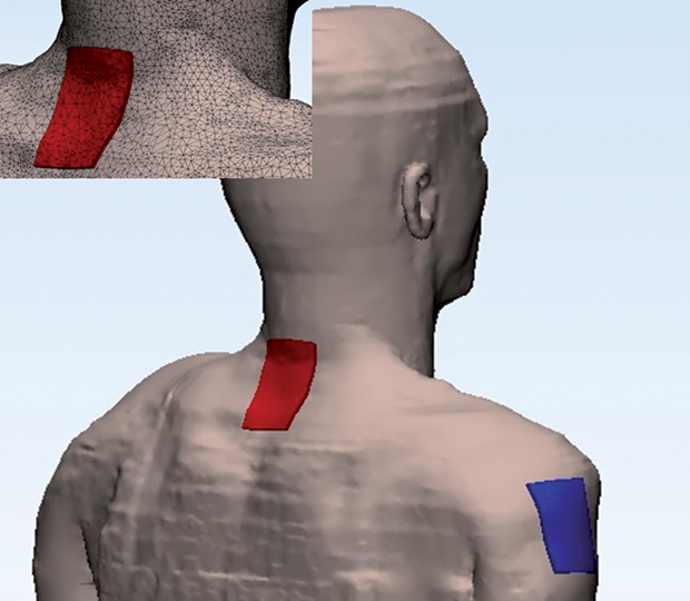
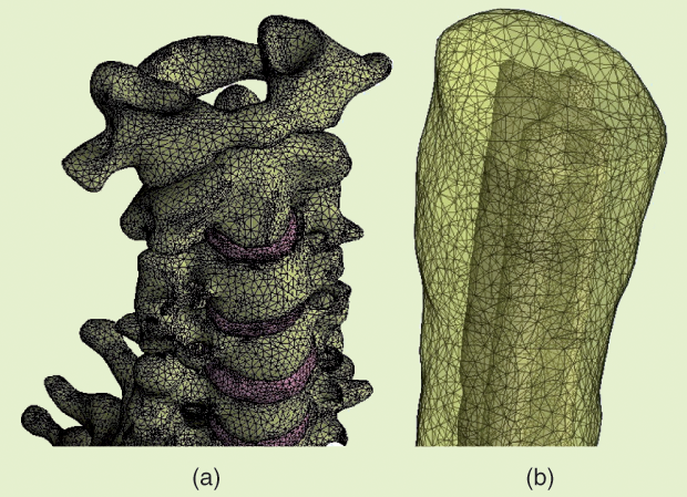
The body model was based on the 34-year-old Duke fullbody model from the Foundation for Research on Information Technologies in Society’s Virtual Population family [9]. Surface meshes corresponding to 12 different tissues were retained: skin, fat plus subcutaneous adipose tissue, muscle, heart, lung, viscera, bone, dura mater, vertebrae, intervertebral disks, CSF, and spinal cord. A surface mesh describing the WM/GM interface in the spinal cord was added manually, and a volume mesh was generated. The electrode configuration used for cervical tsDCS is illustrated in Figure 3. Details of the meshes representing the vertebra, discs, and spinal cord are shown in Figure 4, and the electric field induced in the spinal cord by a current of 2.5 mA is shown in Figure 5. The maximum magnitude is 0.27 V/m, but the scale was capped a t 0.2 V/m. Note the two local maxima located under or close to the upper and lower edges of the electrode. Between these maxima, the field is weaker under the central part of the electrode.
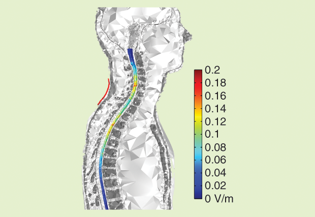
These results illustrate the impact of the complexity of tissue geometry on the electricfield distribution and the importance of the position of the electrodes relative to the target in the cortex or spinal cord. The simulations also provide information about the direction of the electric field in the GM and WM, which may be relevant for neuronal stimulation because the effect of the electric field on individual neurons is known to be directional.
Personalized Head Models
Computational studies have also shown that the electric-field distribution varies significantly between individuals, affected by factors such as head size; the thickness of the scalp, skull, and CSF; and cortical anatomy. However, producing good-quality FE meshes is presently a time-consuming process due to the need for manual corrections. Future improvements in segmentation and meshing routines may speed up this process to the point of making individual anatomical models practicable on a large scale.
Such personalized models are vital for safety reasons in cases of patients with brain lesions, such as from a stroke or tumor, because the presence of lesions could induce high electric-field regions in the normal parenchyma. They would also be useful, even in the case of patients with no brain lesions, to determine which electrode positions optimize the electric field at the target and increase stimulation efficacy.
Multielectrode stimulators have already been developed to improve control over the electric-field distribution in the brain. Amultielectrode system can be used to optimize the electric field at a single target (Neurotargeting, Soterix [10]) or a functional network of targets (StimWeaver, Neuroelectrics [11]). In either case, optimization is based entirely on computational models. Here, too, optimization should be based on personalized models for greater accuracy.
In the future, computational models could attempt to predict the outcome of noninvasive stimulation by combining electric-field models with neuronal models at various scales (single neuron, local circuits, or brain networks). These models would then be amenable to physiological interpretation and validation.
Acknowledgments
Research for this article was supported in part by the Foundation for Science and Technology (FCT), Portugal, under FCT-IBEB Strategic Project UID/BIO/00645/2013. Sofia R. Fernandes was supported by FCT grant SFRH/BD/100254/2014.
References
- Products/STARSTIM. Neuroelectronics. [Online].
- Digital brain health. Neuroelectronics. [Online].
- DC-STIMULATOR—Stimulators for cranial electrotherapy and neuroscientific research. NeuroCare. [Online].
- NeuroCare. [Online].
- Soterix Medical HD-tDCS: High definition-transcranial direct current stimulation. Soterix Medical. [Online].
- Soterix Medical. [Online].
- HDCKit. Magstim. [Online].
- Magstim. [Online].
- Virtual population. ITIS Foundation. [Online].
- Neurotargeting guided current delivery. ITIS Foundation. [Online].
- STIMWEAVER-P. Neuroelectronics. [Online].